
ToF (Time-of-Flight) Algorithm
Time-of-Flight (ToF)
Time of Flight is the most promising technology in 3D depth sensing and mapping. It is also known as near range solid state Lidar. Compared to Stereo Vision 3D technology which depends on complicated algorithm and requests heavy computation, the mechanism of ToF is direct. Therefore, ToF is comparatively in a compact form and able to generate real-time depth data without heavy computing load or high power usage. Compared to Structure Light, ToF has a long working range and is less affected by the interruption from environment light.
Kinds of ToF
- Pulse ToF (pToF)

- Gated Imaging ToF

- Continuous Wave ToF (cwToF)

Introduce Continuous Wave ToF (cwToF)
- What Is a Time-of-Flight Sensor?
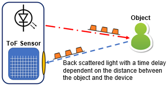
Time of flight sensors measure the time it takes something to travel a distance through a medium. Typically, this is the measurement of the time elapsed between the emission of a wave pulse, its reflection off of an object, and its return to the ToF sensor. A time of flight camera is a device that utilizes ToF measurement to determine distances between the camera and objects or environments, creating images generated by individually-measured points. Applications of ToF cameras include laser-based scanner-less LiDAR imaging systems, motion sensing and tracking, object detection for machine vision and autonomous driving, topographic mapping, and more. But how are these measurements achieved?

- Milimeter-Level Precision ToF Cameras
Light and radio waves travel at nearly 300,000,000,000 mm/s, which translates to ~3.3 ps for a wave to travel 1 mm (and another 3.3 ps to return). That means, if you want a device that can image all the objects in the room you are in and you want ~ 1 mm resolution, your timing electronics would need picosecond resolution. That translates to a clock speed of hundreds of GHz. It is neither easy nor economical to design electronic circuits that operate at those frequencies, so designers had to come up with a way to work at lower frequencies if they hoped to bring the devices affordable to the consumer space. Two common methods exist to achieve millimeter-level precision while working with reasonable, sub-GHz frequencies:
- Determining Distance by Phase Shift of an Amplitude Modulated Wave
Let's say you're looking to map out a small office or large living room with a maximum length dimension of 15 m. To determine an appropriate operating frequency for that length, use c = λ ⋅ f where c is the speed of light (c=3x10⁸ m/s), λ is one wavelength (λ=15 m), and ƒ is the frequency. In this example, ƒ=20 MHz, which is a relatively easy frequency to work with. It all begins when a bright light has its output modulated with a 20 MHz sinusoidal signal. The light wave will eventually reach an object or the wall and it will reflect and reverse directions. A dimmer version of the original modulated light will return to the receiver. Unless the object is exactly an integer multiple of 15 meters away, the phase will be shifted by some amount. The phase shift can be used to calculate the distance the wave traveled.
- How to Measure the Phase Angle of a Sinusoid
So, how do you quickly measure the phase angle of a sinusoid? That involves measuring the amplitude of the received signal at four equally spaced points (i.e., a separation of 90° or 1/4 λ).
I have attempted to illustrate the relationship between the measurements and the phase angle below. The ratio of the difference between A0 and A2 and the difference between A1 and A3 is equal to the tangent of the phase angle. ArcTan is actually the two-argument arc-tangent function which maps appropriate quadrants and defines when A1=A3 and A0>A2 or A2>A0 as 0° or 180°, respectively.
In the illustration bellow, the far left of the graph has two vertical number lines that show the result of subtracting A0 and A2 and A2 and A3 . The measured values are shown as vertical lines in the sinusoid graphs in the middle.
Note that this graphic does not take reflection into account (which would effectively shift everything 180°).
- Determining Operating Frequency for a Given Distance
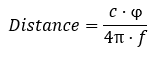
Where c is the speed of light, phi (φ) is the phase angle (in radians), and ƒ is the modulation frequency. Measuring the actual time-of-flight of a photon requires 333 GHz electronics. This method requires a maximum of 4x the modulation frequency, which in this case is 4x20 MHz=80 MHz. This is a phenomenal reduction in resources. But you’ll be happy to know that some clever engineers found a way to reduce the maximum frequency even further.